CoreModel
CoreModel provides the ability for bus controller models to expose their virtual bus interface over-the-internet and the CoreModel API to attach remote peripheral models to a virtual machine (VM). As of February 2024, there are 3 machine types available on AVH that support CoreModel, the Raspberry Pi 4-B, the NXP i.MX 8M Plus, and the NXP i.MX 93, with more models supporting CoreModel to come in the future.
CoreModel supports multiple standard device interfaces, the currently supported interfaces include UART, I2C, SPI, CAN, GPIO, and USB Host.
The sections below give an example of using CoreModel for GPIO monitoring and control.
CoreModel GPIO deep-dive
The sections below provide a technical deep-dive, where we will explore using the CoreModel GPIO virtual interface to monitor and interact with the Raspberry Pi 4-B (RPI4B) GPIO controller. Setting up the RPI4B virtual machine with gpiod on Arm AVH and a suitable development environment for CoreModel either with Windows WSL or directly on Linux, then use the publicly available GPIO example to explore and transform it into a remote virtual device with buttons and an LED.
Development Environment and VM setup
The CoreModel development setup is very minimalistic and doesn’t need much to build on Ubuntu. CoreModel development can be done directly on Ubuntu-20.04 or using Ubuntu Windows Subsystem for Linux (WSL) version 2.
Set-Up Microsoft Windows
Windows can be set up and configured natively for development with WSL or in a VM. To simplify the Windows setup, we use the development VM provided by Microsoft for the walk-through.
The development VM comes preconfigured for development on Windows and has WSL v2 enabled with Ubuntu installed.
Configure Windows Subsystem for Linux (WSL)
When first starting up WSL it will have you go through initial Ubuntu creation/configuration providing a user and password. Once the configuration is complete, the WSL networking name service will need to be established to allow external DNS resolution. By default, WSL is configured to have a private name service with the host VM.
Inside WSL the /etc/wsl.conf will need to be modified to disable auto-generation of /etc/resolve.conf containing the nameserver address that needs to be modified.
Using root permissions, add the following to /etc/wsl.conf:
Once the file has been saved, WSL will need to be restarted. In another PowerShell window run the following to shut down and restart the WSL instance.
Now that WSL is using the new /etc/wsl.conf, the /etc/resolve.conf can be generated with your preferred public name server.
After saving the file it will need to be made immutable and WSL to be restarted like before.
Now that the WSL network configuration can resolve external DNS the Linux setup section can be followed to finish up development configuration inside WSL.
Visual Studios code (VScode) setup
The Windows development VM only comes with Visual Studio Community preinstalled and will not be used during the walk-through. VScode can be found here and installed on the Windows VM. VScode simplifies the integration of WSL using remote development tools. Once VScode is installed the remote tools can be installed directly by the extensions manager or by following the link and clicking install. The WSL extension is installed as part of the remote tooling that enables VScode to start from inside WSL by using code . in the repository. The tool will synchronize code edits done with VScode directly with WSL.
Ubuntu Linux Setup
The CoreModel API build requirements on Ubuntu 20.04 are minimal.
Create the Virtual Raspberry Pi 4-B VM
Using a preexisting RPI4B instance or the creation of a new RPI4B instance, gpiod will need to be installed.
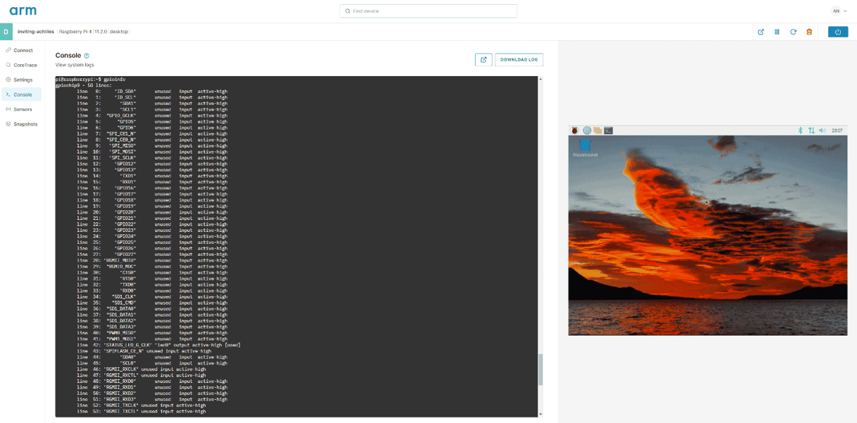
The gpiod application provides the ability to interact with GPIO pins through the terminal. There are three main commands that we will be using with gpiod: gpioinfo, gpioset, and gpioget.
Using gpioinfo, we can query what the GPIO interface is named. The name of the GPIO interface will need to be supplied to the other utilities to get or set the pin’s logical value.
Pins 15, 16, and 17 will be used throughout this deep dive.
Not all pins show that they are being used by gpioinfo. Even if they are stated as unused, there could be a hardware model using the pin or attached to its secondary functionality. If there is a device attached to the pin, it could create unexpected behavior.
Using gpioget, we can get the logical value of a pin. The pin number is required to get the pin’s value.
Using gpioset, we can set the logical value of a pin. The pin number and the logical value are required to set the pin’s value.
SSH Configuration
SSH credentials will be required to attach CoreModel to the VM. If you do not already have credentials in your project, they can be generated and added as shown in Quick Connect guide.
If you have SSH credentials on another development VM, pull them into the WSL environment.
The WSL network is NATed with the Windows VM, getting the credentials this way was done to avoid setting up port forwarding.
Get Started With CoreModel
With the development environment and VM setup, we can configure a connection to the VM’s private network and see what virtual buses CoreModel provides access to on the RPI4B.
Connecting to CoreModel– SSH Proxy and Port Forwarding
Before we can jump right into using CoreModel we will have to establish a connection either by VPN or by using SSH to access the service IP of the VM at port 1900. Port 1900 is the default port for CoreModel connections. To simplify establishing a connection in a new shell we can use SSH to connect to port 1900 and have the traffic present at 127.0.0.1:1900.

Which Controller? – Finding the GPIO Controllers Name
CoreModel provides a way to query the VM and see what virtual buses are present. Out of the box, the GPIO CoreModel example requires the name of the GPIO controller to be provided. Some machine types have multiple GPIO controllers, and the naming convention usually is based on vendor controller names.
Using the list example, we can interrogate any VM to get a list of buses and their names.
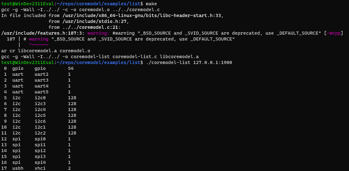
The RPI4B GPIO bus is named gpio and has a total of 54 pins that can be inspected or driven. Any pin can be driven, even if there is a model or peripheral using it, which can cause unwanted or undefined behavior.
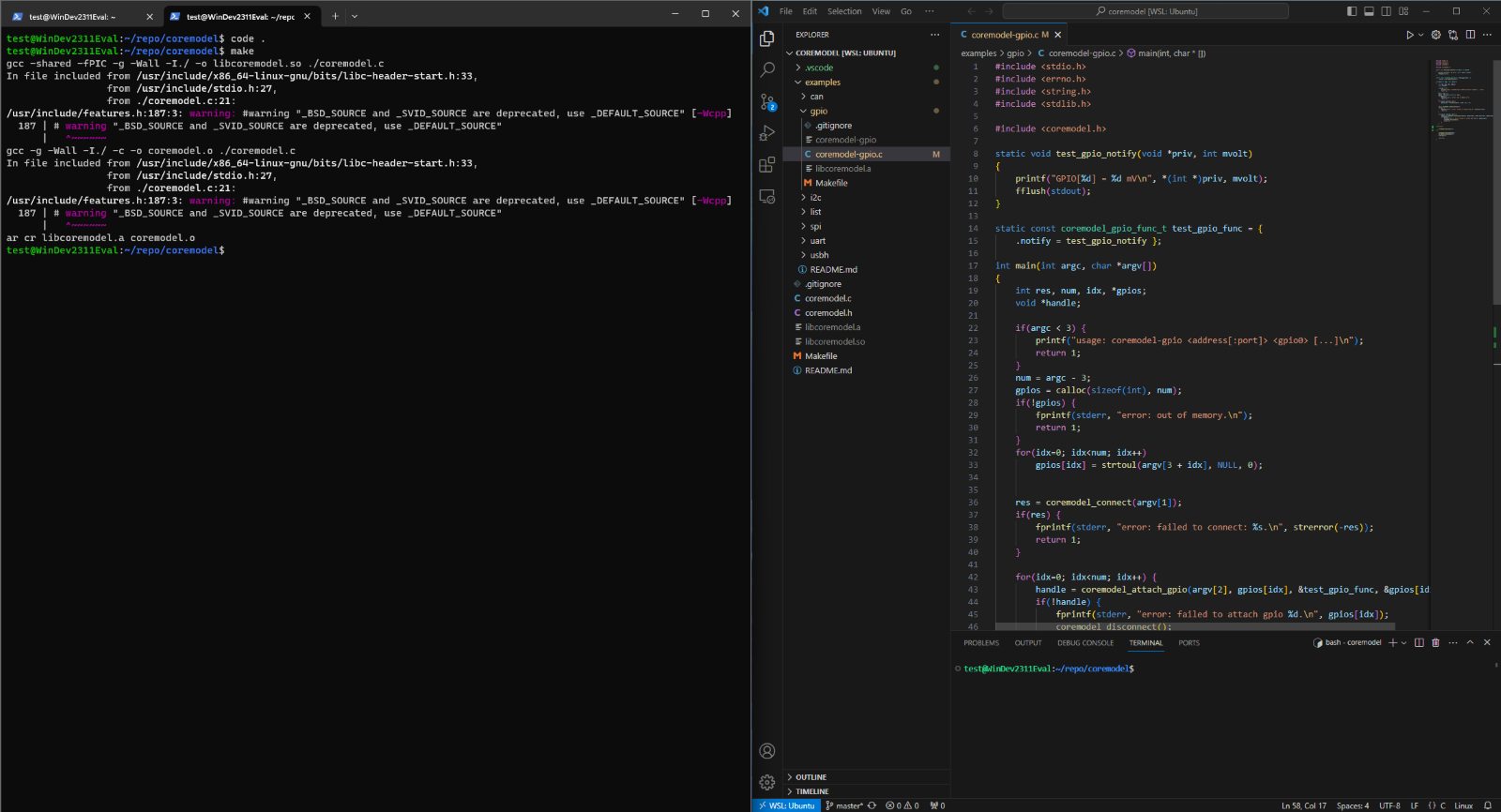
Listening to Pins – GPIO example
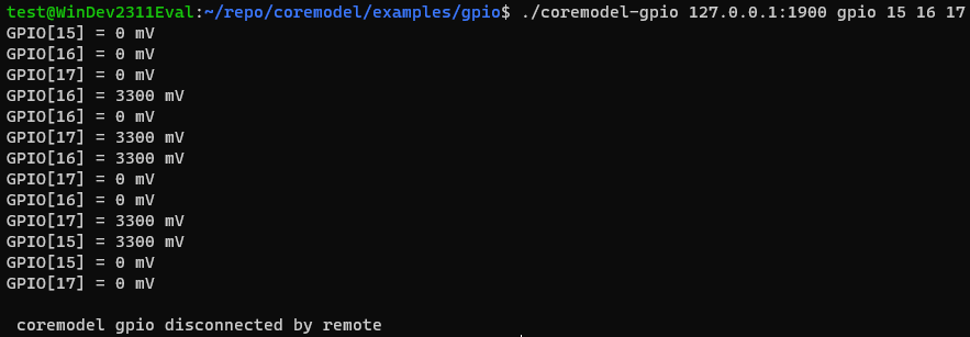
The CoreModel GPIO example out of the box is a pin listener, it will listen to any number of pins you provide it at run time.

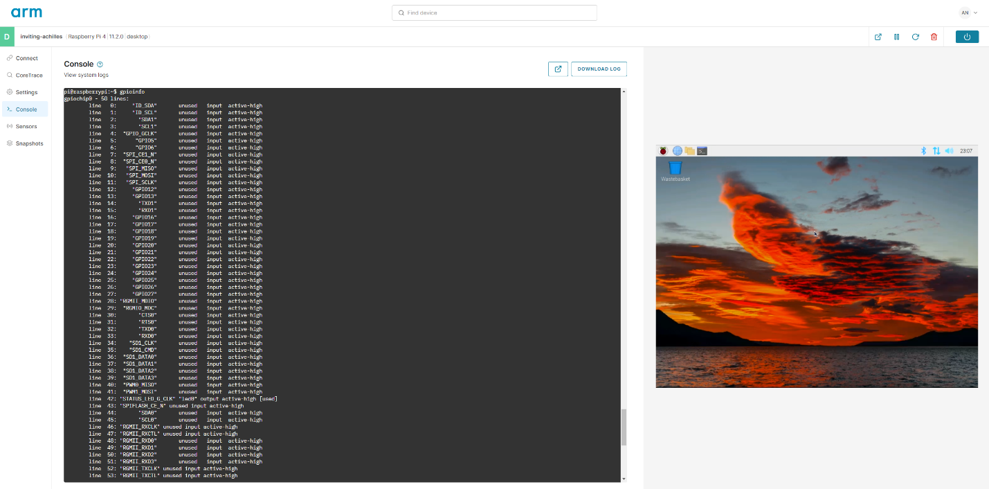
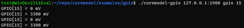
With the notify function attached to the pins, we can toggle the pin value with gpioset and see the result almost immediately.
![]()
Only the pin values that have changed will be notified to print out their active value.
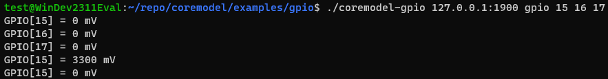
The notify function provided to CoreModel gets called and prints out the values seen above.
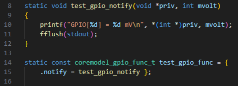
The GPIO example attaches the same pin notify function to each pin, each pin can have independent notify functions provided, before starting the main loop.
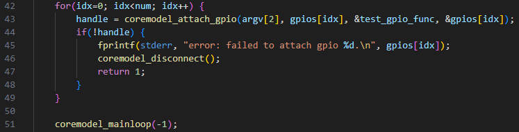
The main loop can be provided with a value in microseconds, a value of -1 will run indefinitely.
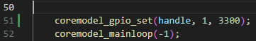
Setting Pin Voltage
With the base CoreModel GPIO example we can modify it to set the voltage of a given pin using coremodel_gpio_set.
The coremodel_gpio_set function requires the pin handle returned by coremodel_attach_gpio. Setting drven to 1 will notify CoreModel to drive the millivolt value mvolt.
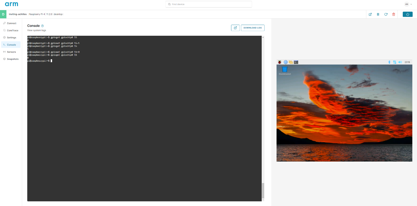
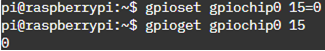
Before running the modified example, we can set pin 15 to 0 and verify it is 0 with gpioset/gpioget.
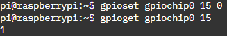
With the code changes, CoreModel gets notified of the original state and also notified of the changed pin value.

The logical change of the pin can be seen inside the VM with gpioget.
![]()
CoreModel will drive the pin’s value high even if gpioset drives it low.
The notify function will be called on every value changed in the order the notify events occurred.
Before moving forward make sure to disable the pin from being driven. Even with coremodel-gpio disconnected, CoreModel will continue to drive the pin high until the VM is restarted.
Let's Get Blinky
We can use the CoreModel GPIO example as a base to model a simple device with an LED using pins 15, 16, and 17 of the RPI4B for control and sense. Pin 15 and 16 will be virtual buttons, controlled by the RPI4B, exercising the attached model and 17 will be monitoring the LED’s state. One button will control the LED and the other button will shut down the model and detach it from the virtual GPIO bus.
Adding State
The base GPIO example is a barebones listener with no internal state. The state can be provided to the notify function by the priv value during attach. Right now, a pointer is being provided to the pin’s index. Before we get to that, let’s define a structure to manage the state of the model.
The definition of PIN_NUM is taken from the total number of pins the virtual device has present. When modeling a peripheral device, it is generally good practice to have a way to track global and local states for the device. The pin structure contains a pointer to the global state which will allow us to do more complex or higher-level device functionality. The pin_handle is the handle that is generated during attach, having this will allow other pins to be updated during notify.
Modifying Notify
Now that we have a structure for the pin and the global state, we can do a bit more advanced functionality in the notify function. During the attach process that will be covered later, we will provide the priv value the pointer to the pin structure itself. This will allow us to have the pin, the global state, and a way to calculate the pin number. Below is a complete notify function to treat pin 15 as the shutdown button and pin 16 as the toggle button of the LED on pin 17.
Note that when pin 16 is setting the value of pin 17 it checks to make sure a handle exists. Handles are generated during the attach process and if a pin was not assigned a handle calling it is undefined. The pin->mvolt is assigned last to allow having the new and previous value at the same time if it is needed.
The Main Function
There are a few places we will need to change to get the main loop operational with the new state and notify functions. Let’s put first things first and allocate the new state structure at the beginning of main just after the other variable declarations.
Jumping to the end of main, make sure we free the allocated state and provide a message when disconnecting.
The loop attaching the notify function will need to be updated to make sure the state is properly available, and the correct pointer is provided to the notify function. We will also add a check, so invalid pin indexes are not used.
After the pin handle is checked we can add the handle to the state of the pin.
We can now replace the original main loop that was configured to run indefinitely.
The final step is to make it so each pin that is attached resets the value, disables it being driven, and then gets detached.
With these modifications the simple GPIO example has transformed into a blinky LED example.
Running Blinky
Using gpioset, we can toggle pin 16 as if we are pushing a button to have the LED on pin 17 change. When you are ready to shut down the model and have it detach all pins set pin 15 high.
You will notice that the first time pin 16 is set high, pin 17 does not get notified. This behavior is due to the value originally being 0 and there was no change in value needing to be notified.
Expanding Peripherals Remotely
Going through transforming the GPIO example to a blinky example, we covered the general usage of set and notify behavior of CoreModel GPIO along with some best practices. The blinky example is just the start of a peripheral modeling journey and could be further expanded. One expansion could even be an external interrupt handler by having multiple notify functions handling different behaviors.
CoreModel GPIO APIs provide a robust way to expand and interact with a VM’s virtual GPIO bus, enabling remote GPIO modeling.
Revolutionize Your IoT Device DevOps with Corellium
Modernize the development of your IoT embedded software and companion mobile apps with virtual devices that tie into your SDLC process. Learn how Corellium’s high-precision virtual models enable faster development, enhanced security, and lower costs.
Book a meeting to learn how Corellium accelerates software development lifecycles with Arm-native virtual models and powerful tools and APIs.